
| Archaeology
Defined The Feature System Stratigraphy |
 |
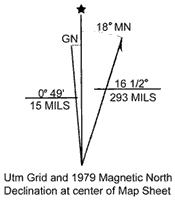
| Figure 1. Declination. |
 |
| Figure 2. Reproduced section of U.S.G.S. quad "Firth, Idaho." Site locations will typically emphasize topographic landmarks and permanent features like maintained roads, wells, streams, and telephone lines. |
-The archaeological site must be plotted on a U.S.G.S. quad sheet and the legal description (T-R or UTM) noted. Location should include a brief description of site locale, emphasizing easily recognizable landmarks (topography, streams, roads) and describing access to the site area.
-The crew will have to decide if reference is to magnetic north or true north, adjusting for declination as indicated on the U.S.G.S. quadrangle (quad sheet).
-The crew uses the Brunton to shoot a cardinal reference line (N-S or E-W). A stake marks the datum to be established and another marks the end of the line. If this baseline is to be used for a test trench, the crew may run a metric tape from stake to stake, marking off one meter excavation units or squares.
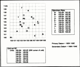
-The grid should be numbered within the NE quadrant, assuming a reference datum set well off the site surface to the SW. Usually, the grid datum is set as 100N 100E. This convention will allow for expansion back to the SW if necessary and ensures consistency by allowing only grid references drawn within the quadrant defined by the North and East axes.
-(Figure 2) A sketch map should be made of the site prior to excavation. This sketch map should indicate major artifact concentrations, locations of stream channels and roads or other features, and the layout of the cardinal grid line.
-It is very important at this juncture that the field crew note all surface evidence that might pertain to the nature of site disturbance.
-If testing is required, grid units should now be selected for excavation. Generally, any testing should try to randomize the distribution of excavation units. This proviso should also be intepreted, however, with common sense. If cultural features are visible on the surface or in stream erosion banks, or if artifact distributions show obvious clustering, the sample should be stratified and encompass arbitrary placement of excavation units.-All horizontal and vertical measurements must be taken from the primary or secondary site datums.
-All excavation squares and excavation levels must be labeled within the establish quadrant of one meter grid squares.
 |
| Figure 3. The site grid reference system. |
Concern for adequate CONTROL must also dictate excavation strategy:
Mundane but very important: Make sure that the excavation unit is absolutely square (an error at the beginning is a fatal flaw in the analysis and publication). Excavators should use two metric tapes and the concept of a 3-4-5 triangle to square unit corners.
Mundane but equally important: Make sure that all excavation units are designated by their southwest corner referenced within the NE site grid system. A common mistake is to confuse excavation unit coordinates as excavation progresses.
Mundane again, but oh so common a mistake: Make sure that the strings on the stakes are crossed on the inside so that excavation margins do not prematurely remove the stakes.
If level readings are being taken from the SW corner of the excavation unit, be sure to notch the corner stake rather than letting the level string slide down as the site surface erodes. This string elevation will be shot relative to the primary datum elevation.
Excavation will normally proceed in arbitrary 5 cm or 10 cm horizontal levels within the excavation units. As excavation expands into adjacent units, arbitrary levels will generally be abandoned for natural or cultural levels. A this point, elevations will be taken on the surfaces of the naturally sloping and diving strata.
 |
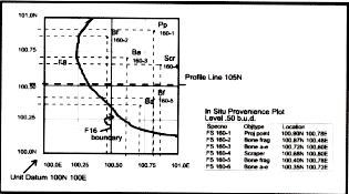
| Figure 4. Plotting the position of artifacts on the floor of an excavation unit. |
As excavation proceeds, the crew is recording tactics and observations in the feature system forms. Done correctly, this record supplies the information that will be sought by analysts, report writers, and other researchers.
Rigor is essential. Remember that excavation is destruction, and is only justified if the utmost care is taken to record all relevant information.Barker, Philip
1993 Techniques of archaeological excavation. London: Batson.
Hester, Thomas, Harry J. Shafer and Kenneth L. Feder (eds.)
1997 Field methods in archaeology. 7th ed. Mountain View: Mayfield.
Jaukowsky, Martha
1980 A complete manual of field archaeology. Englewood Cliffs: Prentice Hall.