| Archaeology
Defined The Feature System Mapping the Site |
Excavators will construct their profile excavation unit wall by excavation unit wall. Ideally, the stratigraphic sections will record points of intersection and the angle of repose across the full extent of the unit. Figure 1 presents an idealization of stratigraphic profiling procedures (horizontal and vertical reference lines).
 |
| Figure 1. A schematic stratigraphic profile showing drawing and recording conventions. |
As shown, a great deal of information can be presented in a properly drawn strat profile. A line level sets the horizontal reference line, which is marked off in 10cm units and vertical reference lines are established along which measurements are taken with a metric tape. Points are established that mark the uppermost, lowermost, and horizontal extent of all cultural and natural features. FS numbers assigned are shown on the profile as symbols indicative of diagnostic artifacts or radiocarbon samples. The profile should supply all information that the excavator or analyst needs to maintain control of the excavation and subsequent analysis. The depiction of key reference points is simplified by conventions like vegetation drawn on the surface and diagonal lines drawn through stones in the sterile level.
Each profile page should have a key to symbols and an descriptions of important features and field specimen lots. Notes should be indexable and usable for subsequent analysts. For example, radiocarbon samples with high potential should be identified on the strat and on the accompanying notes section. Similarly, diagnostic artifacts should be located on the strat and listed by their field specimen number.
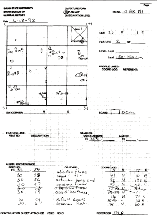
Profiles are generally drawn on Continuation Sheets to a 1:10 scale consistent with that used in Field recording form #2. This form is used for drawing plan maps of feature extent, surfaces or excavation levels. Use of a consistent scale is key since we want to be able to scan these records into our computer data base and later draw profiles and plan maps depicting broad sections of site stratigraphy and activity surfaces.
 |
| Figure 2. Filled-out Form 2 from excavations at the Indian Rocks site, 1992. |
Boggs, Sam
1995 Principles of sedimentology and stratigraphy. Englewood Cliffs: Prentice Hall.
Courty, Marie A., Paul Goldberg and Richard Macphail
1989 Soils and micromorphology in archaeology. New York: Cambridge University Press.
Hassan, Fekri
1978 Sediments in archaeology: Methods and implications for paleoenvironmental and cultural analysis. Journal of Field Archaeology 5:197-213.
Keeley, Helen and Richard Macphail
1981 A soil handbook for archaeologists. Bulletin 18. Institute of Archaeology, London.
Stein, Julie
1988 Interpeting sediments in cultural settings. In Julie K. Stein and William Ferrand (eds.), Archaeological sediments in context. Orono: Center for the Study of Early Man.